
Copyright © Sinor Electronic device Co., Ltd.All Rights Reserved 粤ICP备16001692号 Website construction: 300.cn zhuhai

TAOBAO

Copyright © 中企动力科技股份有限公司 All Rights Reserved 豫ICP备10099324号 网站建设:中企动力 洛阳
Solution
一 、schematic diagram of on-line oven

二 、Description of feeding system
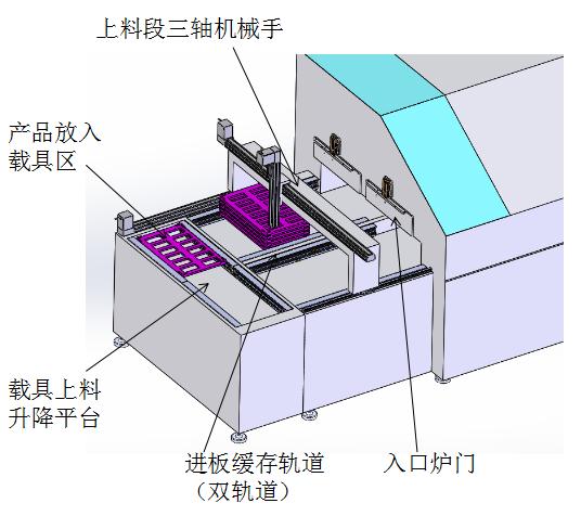
1. The vehicle enters the loading lift from the reflow line under the oven. Then, the carrier is transported to the product and put into the carrier area by a lift, and the manipulator waiting for the glue section will put the PCB into the vehicle.
三、Description of backflow system of materials and tools
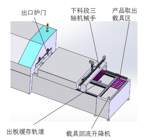
1. The vehicle comes out of the tunnel furnace and is connected by the exit plate buffer track and stops at the designated position.
2. The three-axis mechanical arm of the lower feeding section shall take out the top loading device and place it in the lifting loading area of the product. Then the next station will take the product away.
3. After the product is removed, the no-load device enters the backflow line of the vehicle under the tunnel furnace through the backflow elevator of the vehicle. The no-load tool is then returned to the feeding system by the backflow line.
4. The mechanical arm grabs the second vehicle and puts it into the product loading area, then the no-load vehicle returns to the feeding system. Until all three fixtures are removed and returned.
5. Then, the feed and the vehicle return system shall take out and return the vehicle in another outlet plate buffer track in accordance with the above method.
6. The feed and vehicle return system shall be recycled in this way.
四、Details of the movement of the vehicle into the heating zone and out of the cooling zone

1. Feed operation
A. The lifting cylinder of the platform is extended to support the temporary storage platform, and the three-axis mechanical arm is stacked with three-layer vehicles.
B. The moving module drives the vehicle storage platform to move into the heating zone, and the platform lifting cylinder drops. The vehicle is placed on the board track, and the vehicle is baked in the oven along the track.
C. The temporary storage platform of the vehicle is moved back to wait for the next batch of vehicles to be put in, so as to realize the feed cycle.
2. Furnace action
A. The temporary storage platform is moved below the exit plate & air cooling zone at the same stage, and the lifting cylinder of the platform is extended to the outermost three-layer vehicle.
B. The moving module drives the loading platform to move to the discharging temporary storage area, and the three-axis mechanical arm takes out the three-layer loading device successively to the discharging platform.
C. After taking out the temporary storage platform of the vehicle, the vehicle is moved back to the lower part of the same stage exit plate & air cooling zone to wait for the next batch of vehicles, so as to realize the material discharging through the cycle.
五、Carrier reflow line (bottom reflow)

六、Diagram of oven assembly

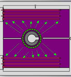
七、Description of the return wind system
 |
 |
1. Heat from the heat pipe is fed by the wind wheel
2. Driven by the motor, the wind wheel will keep turning the furnace
The air duct forms a hot wind hot wind from the air duct network orifice plate into the furnace chamber.
The air in the furnace is exchanged to achieve uniform temperature.
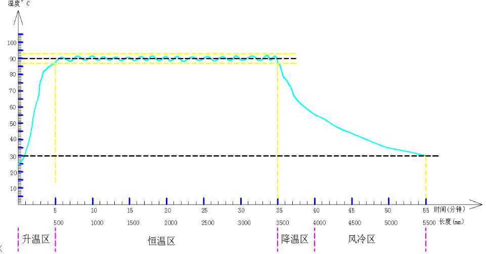
八、Temperature field line

九、Online layout
十、Vehicle arrangement
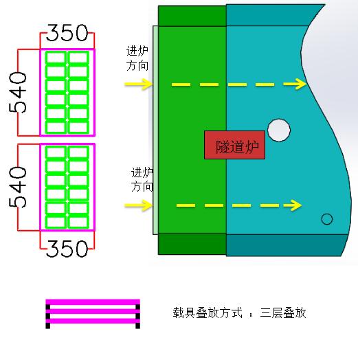
1. The vehicle is stacked in three layers, two rows side by side at the same time.
2. The number of products that can be entered into the tunnel furnace after entering a column of vehicles is :12*2*3=72pcs
3. The number of vehicles in the constant temperature zone is 54
4. The moving speed of the vehicle in the constant temperature zone is 6 meters per hour or 3 meters in half an hour
5. UPH= (12*2*3*9)*60/30 = 1296pcs